
Drone Hyperspectral Data Collection: How to Acquire Hyperspectral Imaging Data From UAV
Published 26.8.2025
By: Petri Nygrén, Spectral Mapping Services (SMAPS)
This article provides a clear and actionable overview of best practices and guidelines that help to enhance the accuracy, consistency, and reliability of UAV-based hyperspectral imaging workflows.
In this article, we cover topics such as:
- System selection and integration: Key factors to consider when selecting the most suitable hyperspectral imaging (HSI) solution for UAV data collection, including technical specifications, payload compatibility, and performance in various environments.
- Best practices for ensuring optimal HSI data acquisition from UAVs, covering flight planning, sensor calibration, data quality management, and operational considerations to maximise the accuracy and reliability of your data.
Typical airborne hyperspectral imaging applications:
Precision agriculture
Health mapping,
Growing stage
Invasive species detection
Law enforcement
Narcotic plants detection; protective tarps
Environmental monitoring
Water bodies assessment,
Sea pollution,
Forest inventory
Geology
Mapping minerals and ore
Defence and
Security
Mapping camouflage material mimicking the colour of the natural surroundings
Vegetation
Measuring traits such as the moisture content of plants to monitor the health of vegetation

Figure 1. Specim AFX hyperspectral camera integrated with a Skyfront Parameter 8 drone for precision agriculture data collection. Courtesy of Alchemy Analytics.
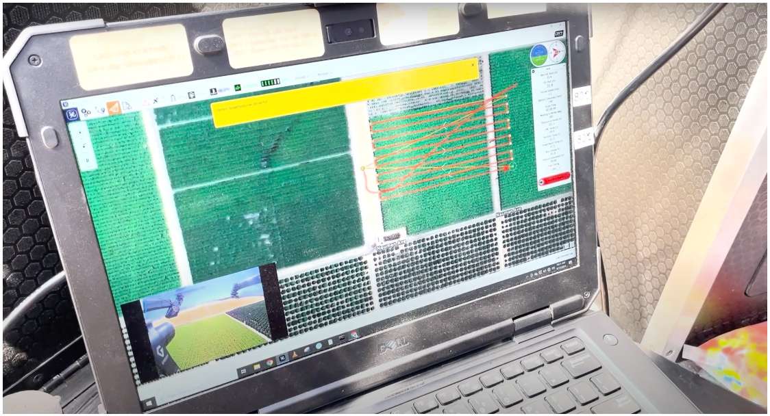
Figure 2. UAV-based hyperspectral mapping of grapevine health and growth stages. Courtesy of Alchemy Analytics.

Figure 3: Airborne VNIR spectral range imaging for environmental monitoring. Data courtesy of SpecTIR
How to acquire HSI data with UAV-mounted Specim AFX
In this section, we dive more deeply into the practicalities of flying the Specim AFX onboard your UAV systems, covering the topics of UAV choice and mounting, flight planning and the workflows for flying with a Specim AFX sensor.
UAV choice and mounting of a Specim AFX sensor
Choosing your UAV for HSI imaging
Use any UAV capable of a 4-6kg payload and with the capability for flying a pre-planned route.
The Specim AFX sensors are roughly 2-3 kg in payload weight; however, it’s never a good idea to choose a UAV that is only marginally able to lift the required payload. We recommend at least doubling, if not tripling, the requirement due to redundancy. This will also lessen the strain on your UAV system and increase its controllability in case of any motor malfunctions.
Most UAV systems today have the functionality to fly pre-planned routes, if not as a standard, then available in the form of a software upgrade. Because the Specim AFX systems start and stop data collection based on the location, certain waypoints must be hit reasonably accurately. This is easier to do with automatic route flying capability.
Choose hexa- or octocopters over quadcopters.
When speaking of multicopters, hexa or octocopters – in other words, six to eight motor UAVs – are recommended for HSI imaging flights. Quadcopters – i.e., four motor UAVs – are not recommended due to redundancy. Losing one motor on a quadcopter in practice means that you are losing two, and the remaining two typically would not suffice to keep your payload in the air, or even less, keep the system controllable. Hence, hexa- and octocopters are the best choice for HSI imaging.
Dedicate your operators and give them professional training.
The air is the most challenging of elements for HSI imaging. Don’t underestimate the importance of dedicating and training your drone operators. This is far more important than the brand of UAV you choose to fly.
Obey the local airspace, ground risk, and registration rules.
Get information from the local CAA (Civil Aviation Authority) on the requirements for the local airspace, ground risk, and registration in the country/region you are flying in.
Gain confidence – fly empty or with dummy weight first!
Above all, gain confidence by flying a lot before putting your valuable sensors on board. Fly empty or with dummy weight to learn your system, how it works, and what its issues are.
Mounting system pros and cons
Fixed mounting
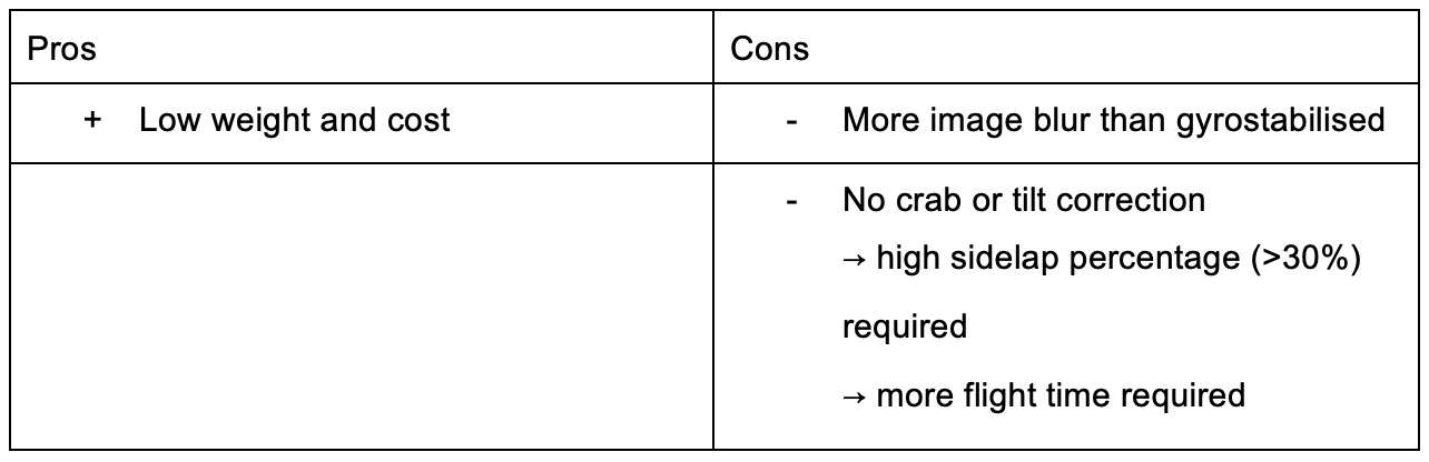
A fixed mounting system offers the lowest weight and cost, although with the downside of more blur than gyrostabilized mountings. Fixed mounts do not correct platform tilting during the flight. The fact that these tilts and crabs are not getting corrected means that you need to plan your project with more sidelap (>30%). The increased sidelap means that you need more flight time to cover an area.
If using fixed mountings, we recommend DAMPERZEN mounts due to the adjustability of their springs, which allows varying the stiffness of your mounting depending on the vibration levels of your particular UAV.
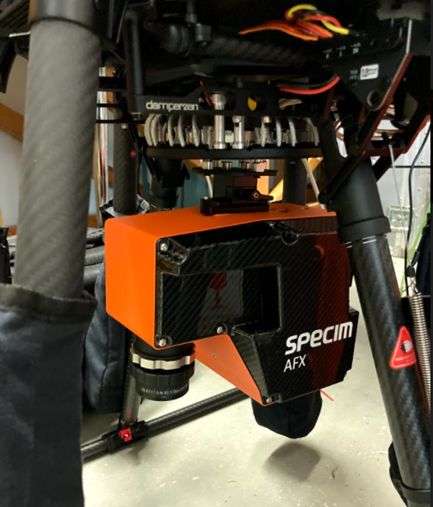
Figure 4: Fixed Damperzen mounts on a UAV with the Specim AFX camera.
Gyrostabilised gimbal mounting
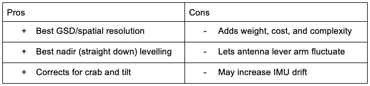
Gyrostabilised gimbal mountings give the best ground sampling distance (GSD) / spatial resolution and are often the best vibration-damping choice. They give the best nadir leveling and correction for crabs and tilts, which means you can lower the sidelap requirement.
The downsides of the gyrostabilized mountings are that they add weight, cost, and complexity. You need to learn to use and adjust them, choose multiple different modes, and check for the center of gravity. The added weight reduces flying time. They allow the antenna lever arm to fluctuate and may increase IMU drift.
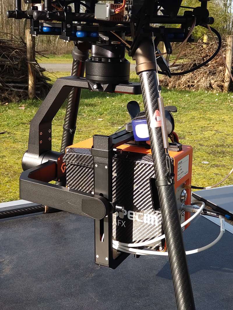
Figure 5: Gyrostabilised gimbal mounting
Flight planning
Basic considerations for planning a flight with Specim AFX
Prioritise SNR over resolution – do not “max out” the sensor!
While it may sound counterintuitive, remember that when using hyperspectral sensors, we are, above all, aiming for spectral resolution, rather than spatial resolution. This is why you should prioritise the signal-to-noise ratio (SNR) over resolution. High spectral resolution means that you are sometimes deprived of natural illumination. Without sufficient SNR, separating fine spectral features becomes difficult through the noise. Therefore, we recommend prioritising the SNR and not maxing out the sensor by pushing it to unnecessarily high frame rates or low binnings.
Plan for min 25-50% sidelap, depending on mounting choice
Plan for the sidelap according to your mounting system. The sidelap depends on a number of factors, such as the wind, as demonstrated in the figure below (Fig. 6). With a fixed mounting system, any tilts and crabs will also risk gaps between the flight lines.
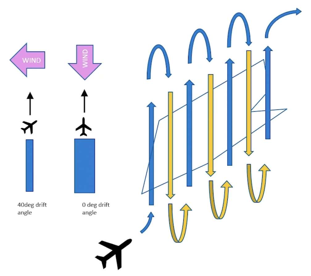
Figure 6: The impact of wind on sidelap. As you can see from the left, strong crosswind will reduce the width of your swath and thereby, the sidelap. The image on the left demonstrates the impact of tilts and crabs on the flight lines.
Plan North-South if possible
If possible, you should plan your flight alignment North-South for several reasons.
Firstly, let’s consider the solar window and line orientation. The solar window means the time of day when you can collect data, which has everything to do with the solar angle, i.e., the angle of the sun from the horizon. A good minimum from the point of view of atmospheric correction is 40°. While it can be reduced to 30°, this will already drastically reduce the illumination – a problem particularly evident in the Northern and extreme Southern latitudes.
One reason to fly North-South is to do with BRDF– Bidirectional Reflectance Distribution Function. In short, this means a difference in illumination between the left and right sides of your swath. Ideally, when collecting HSI data, you want to align the line heading to the direction of the illumination. As this is not always possible, the best average is to align North-South, making the illumination in the line heading at noon. Whatever you do, try to avoid the situation where the illumination is perpendicular to the flight lines. This scenario, demonstrated in the below image, on the right-hand side (Fig. 7), will set your BDRF issues at maximum, making the spectral albedo on the left and right sides of the center of your swaths very different. Particularly in mosaicing, this will be very evident unless corrected algorithmically, which is possible only to a certain point.
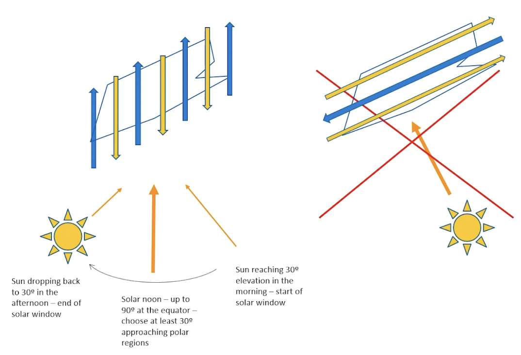
Figure 7: Solar window and line orientation. Avoid the situation on the right where the illumination is perpendicular to the flight lines.
Another reason to align your flight lines North-South is related to file sizes. Non-North-South line heading multiplies the sizes of your files, as demonstrated in the image below (Fig. 8).
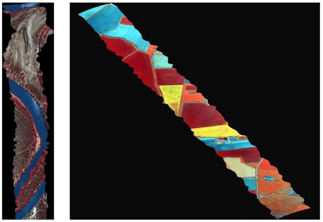
Figure 8: Comparison in image size when aligning flight lines North-South (left) and in other headings (right). A non-North-South flight line resulted in a massive file size compared to the North-South flight line.
Flight planning workflow
Setting kml’s for a flight with Specim AFX10
Two separate kml’s are required: firstly, the UAV flight path, and secondly, the record lines (start and stop) for the Specim AFX10. The UAV flight path kml is entered into the UAV autopilot for automated route-following flight. The Specim AFX10 kml is entered into the Specim AFX web UI, which turns the sensor on when you arrive at the start, and off when you reach the end. When creating your flight path, you should always fly in the same direction as the Specim AFX on-off kml’s.
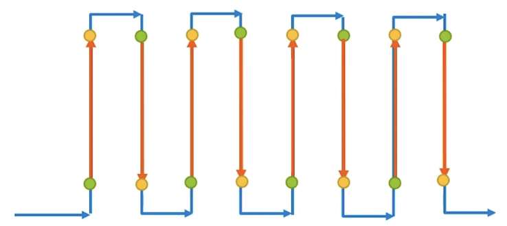
Figure 9: Setting kml’s for a flight with Specim AFX10. The blue arrow is the UAV flight path kml. The red arrow is the Specim AFX10 on/off kml. The green circle indicates the recording starting point, and the yellow circle the recording stop point. Fly the same direction as drawn.
Below, you see an example of how the flight path might look in practice (Fig. 10).
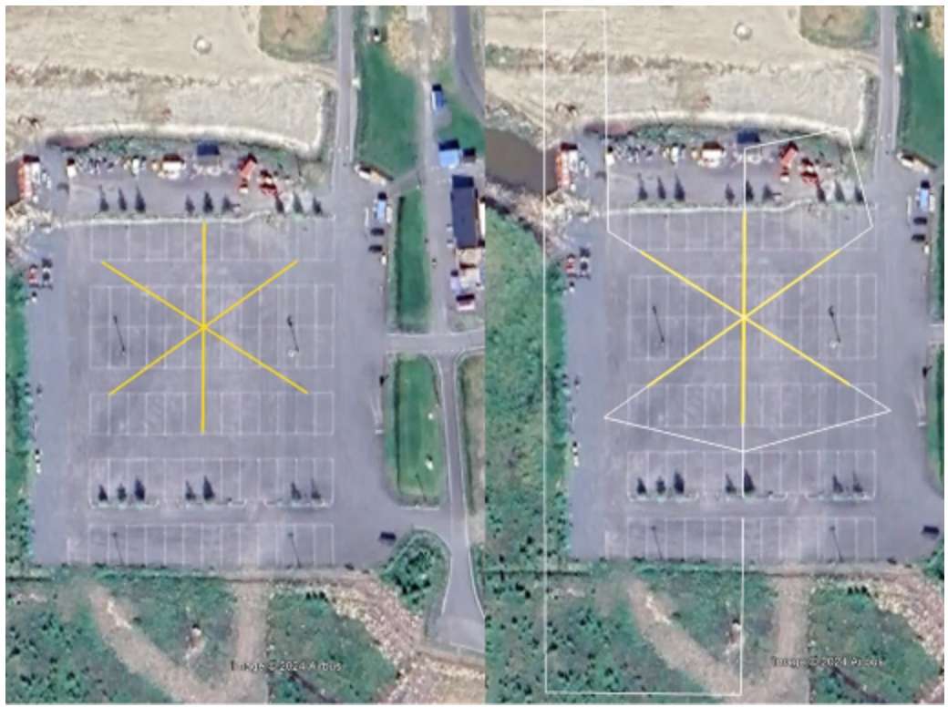
Figure 10: This is the typical boresight cross flown with the Specim sensors. On the left, you see the on-off flight lines, three of them forming a cross. On the right is the actual flight path of the UAV. The flight path for the autopilot use is drawn exactly on top of the on-off lines. The autopilot is flying the route, and the Specim AFX is starting and stopping the sensor as required, separately from the UAV autopilot.
Flight planning workflow step-by-step
- Decide the area delimitation.
- Check the air risk, ground risk, and site facilitation.
- Draw lines in Google Earth with the path tool.
- Draw the flight path to a separate kml for automated route flying.
a. Give flight lines some lead in/out – don’t turn to and from the ends of the collection flight line!
b. Avoid turns in same direction between consecutive flight lines. - Use the flight planning spreadsheet to work out sensor parameters.
a. Binning
b. Frame rate - Check surrounding terrain elevations, obstacles, and where to conduct the IMU alignment run.
Getting started with flight operation
In this section, we go into more detail about how flight operation is carried out in practice. Let’s begin with a few considerations to take into account.
Minimum speed
5 m/s is the minimum speed for maintaining IMU alignment with a single antenna receiver.
The Specim AFX is equipped with a single antenna GNSS/IMU. IMU requires alignment, which it acquires with the aid of the GNSS. The GNSS requires a minimum speed of 5 m/s to give a good heading. Therefore, every flight should start and, at times, also end with an alignment run at a certain speed. In addition, the entire flight should be carried out at a minimum of 5 m/s ground speed. A lower speed will result in the IMU alignment regarding the heading starting to deteriorate. This, in turn, means that there is a certain maximum regarding the frame rate and a minimum regarding the altitude, depending on the kind of terrain being flown over.
Minimum flying height
The minimum practical flying height for Specim AFX10 over medium-reflective terrain is ∼50m (75Hz). The absolute minimum is 37m (100Hz) unless the square pixel and/or full datacube requirement is relaxed.
Boresighting mission
The figure below demonstrates the components of a boresighting mission (Fig. 11). After take-off and gaining the chosen altitude, the first thing to do is an IMU alignment run. This can be flown manually or automatically. The alignment run is done by taking maximum acceleration in your chosen direction up to <10 m/s, continued for <10s, making maximum braking, then continuing backwards the same direction that you came from, also <10 m/s for <10s.
Once you’ve aligned your IMU, you can commence your automatic flight route-following. Now the UAV will start to automatically navigate towards the first Specim AFX flight line where the Specim AFX begins collecting, starting and stopping at your pre-designated points. Notice the turns here are planned in different directions, the first turn being left, then right, and left again. This continues until the end of your mission, however many lines you have. In this case, because it is an example of boresighting, we have three lines. When collecting is completed, you can return to base.
However, if you have a PPK processing workflow at your disposal, the IMU alignment run should also be conducted at the end of the flight. One of the reasons why PPK is the most accurate positioning method is that you can process both forwards and backwards, and if processing backwards, it also needs to start with an alignment run. In this case, after the end alignment run is completed, you can return to base.
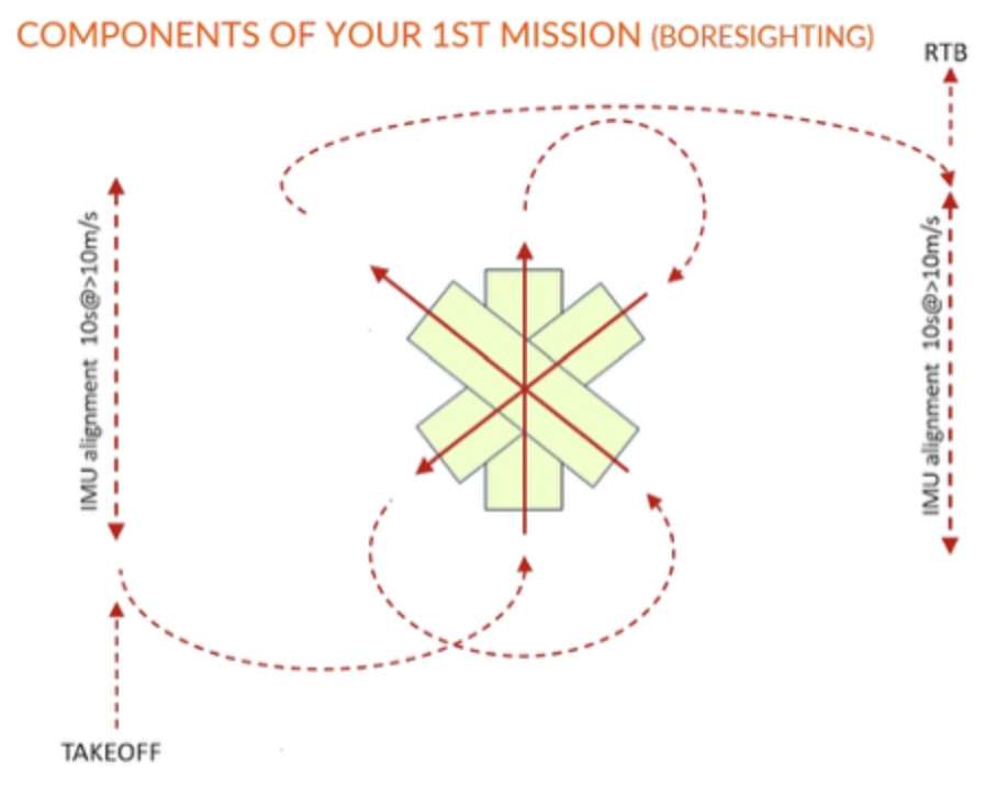
Figure 11: Components of a boresighting mission
Standard (non-boresighting) mission
The components of a standard (non-boresighting mission), e.g., an area coverage flight or corridor plan survey, are the same (Fig. 12). After take-off, you commence with the alignment run, then fly your lines automatically. If you have a PPK processing workflow, you would do another IMU alignment in the end, and return to base.
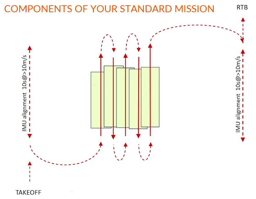
Figure 12: Components of a standard mission
Why is IMU alignment important?
The images below show examples of poor IMU alignment resulting from the alignment run not being run correctly. These problems can be avoided by aligning the IMU properly at the start of the flight, and also at the end in the case of PPK. It’s worth noting that the PPK method helps tremendously, thanks to the double IMU sampling rate available.
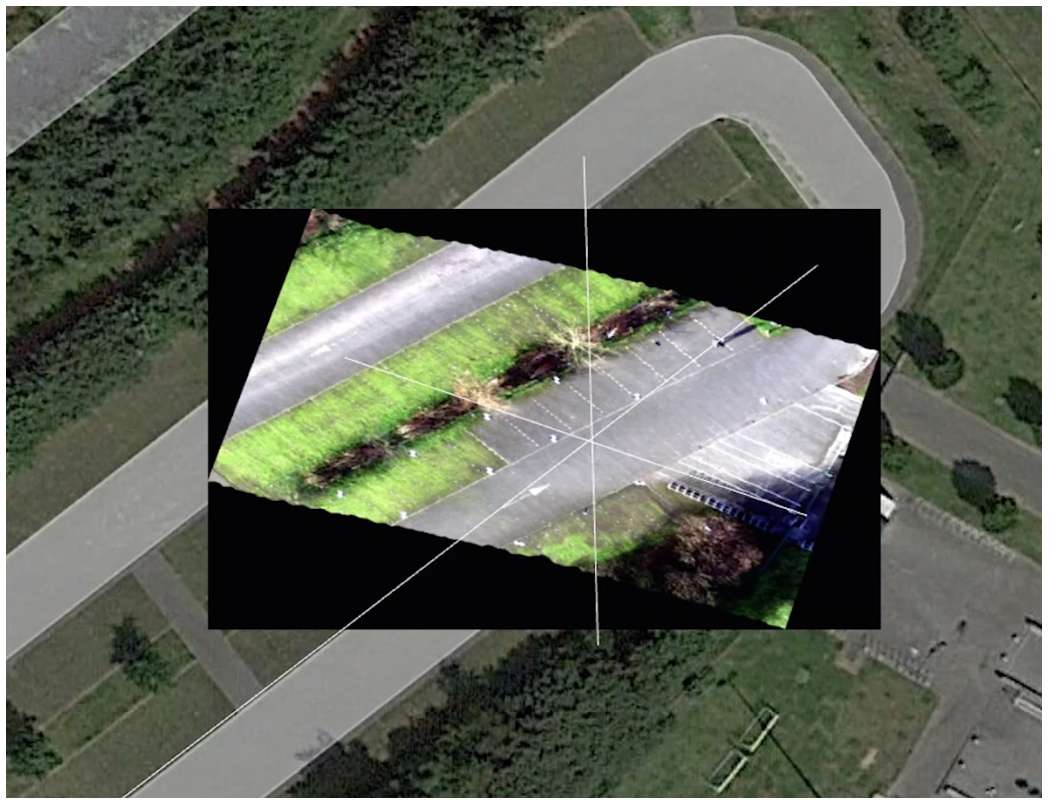
Figure 13: The base image is a georectified Google Earth image. In the middle, you can see an AFX line flown with poor IMU alignment, resulting in the misalignment of the driveways compared with the actuality. The white lines in the image indicate the planned flight lines, which were followed reasonably well. However, the IMU was not aligned properly, in this case due to too slow alignment speed.
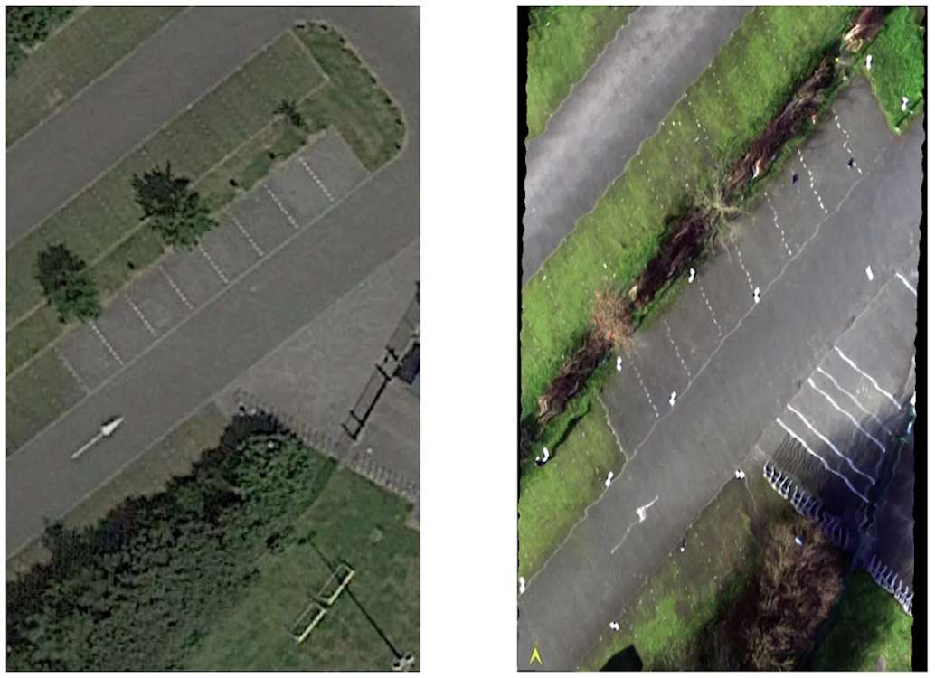
Figure 14: In this image, you can see the result of faulty alignment with an additional wobble.
The Specim AFX series for remote sensing
Specim’s AFX product line offers two compact all-in-one hyperspectral imaging solutions for use in airborne applications covering the VNIR and NIR spectral ranges:

- Compact all-in-one hyperspectral imaging solution for drones
- 400 – 1000 nm (VNIR)

- Compact all-in-one hyperspectral imaging solution for drones
- 900 – 1700 nm (NIR)
Watch the webinar

For more valuable insights on how to optimise your UAV-based hyperspectral imaging (HSI) data collection with practical tips and techniques, watch the webinar How to acquire HSI data from UAV.
Whether you’re refining your current skills or diving into the world of UAV-based hyperspectral imaging (HSI) for the first time, this session with Specim’s Lead Application Specialist Mathieu Marmion and Petri Nygrén, an experienced professional in HSI UAV from Spectral Mapping Services (SMAPS), is tailored to broaden your understanding and enhance your practices.
If you have a question or would like to request a quote, please contact us.
About the author
Petri Nygrén, Spectral Mapping Services SMAPS Oy
Petri Nygrén is a generalist with a specialization in hyperspectral imaging. He has extensive experience in LiDAR technology and medium to large format mapping cameras. With five decades of expertise in geomatics projects conducted in 40 countries, Petri has a deep understanding of the field. Previously, he served as the airborne hyperspectral product line manager at Specim, where he was involved in research and development, production, test flights, support, marketing, and sales. His long career spans both service provider and sensor manufacturer roles, giving him a unique perspective and a strong understanding of client needs.
